Using Modular rigging tools for Maya
In this section, we will rig a simple character from scratch using modular rigging tools. For this tutorial, I’ll try to explain how to use the tools at the same time, but for more details, you can see its documentation here. In a summary, here are the steps necessary to do for the process of rigging a character:
- Define and place the modules for all of character parts
- Set up module parenting
- Modify the module proxy geometry (if applicable)
- Save a module collection for the entire character for reuse
- Create a character from all the defined modules to generate the final joints and then save a template
- Bind the character geometry to the skin joints
- Apply control rigs to the character joint hierarchies
- Animate !
Define and place modules
Leg modules
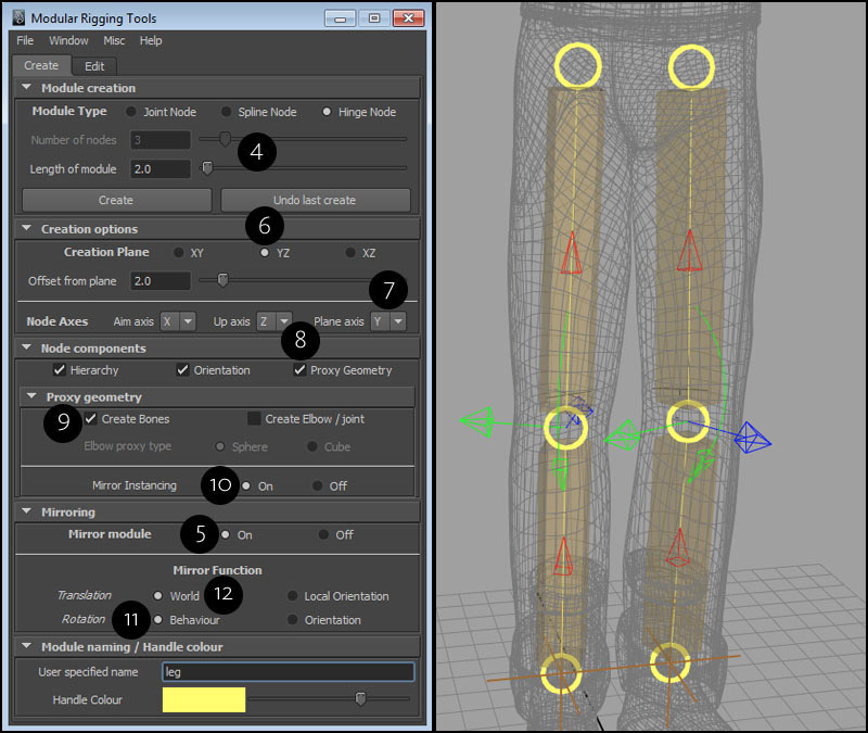
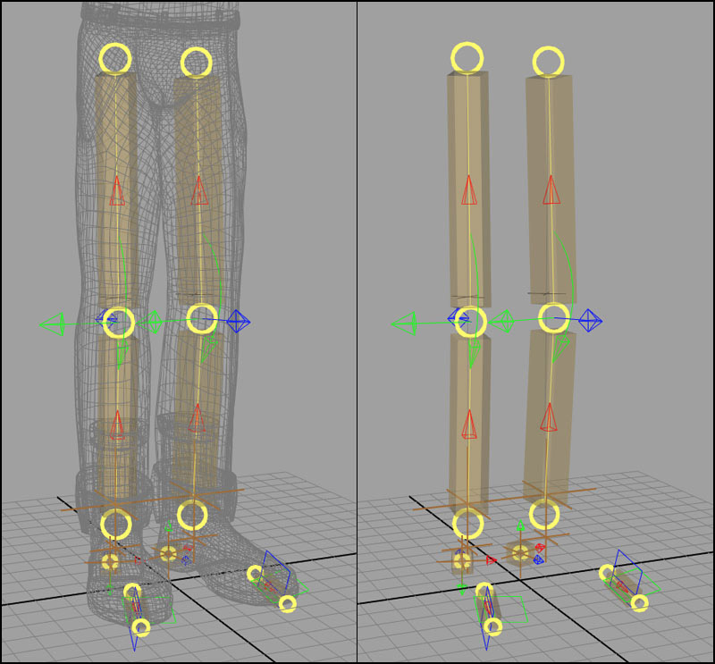
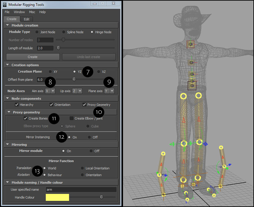
We’ll start by creating the modules for the legs for a character. For doing this, first we have to select the type of module and specify options such as its start length and number of nodes (4). The type of a module which is to be created is related to the control rig which can be attached to manipulate the movement of a body part. Since we want an IK control for the legs, we will create a mirrored hinge module (5). A hinge module consists of three nodes in a hierarchy on a plane. A mirrored hinge module consists of two hinge modules ‘offsetted’ from the YZ plane (6). Therefore, we will keep the plane axis as Y (7) which is parallel to the module’s creation plane as YZ . This configuration will give us the local axes for the final leg joint, where X will be aim or twist axis and the hinge will rotate along Y axis. For this tutorial, we will enable proxy geometry (8) with only create bones (9) option enabled, since we want to create proxies along the length of the lower and upper legs and not on the joints. Mirror instancing (10) is enabled which will allow the proxy geometry of a module in a mirrored module to be a mirrored instance of the other. We will also keep the mirror rotation function for the final joint as ‘Behaviour’ (11) and the translation function as ‘World’ (12) , since for translation, we want both the leg IK translation controls to move in the same direction. One thing to be noted here is that with a mirrored module, we only need to adjust a module and its attributes on either side and the other will follow.
We can also create mirrored modules for the both feet and the heels. It is necessary to create for the heel because the position of the module will generate the heel joint as a pivot required for movement of the foot.
For constructing the modules for feet, we create a mirrored joint module with two nodes and an arbitrary length.
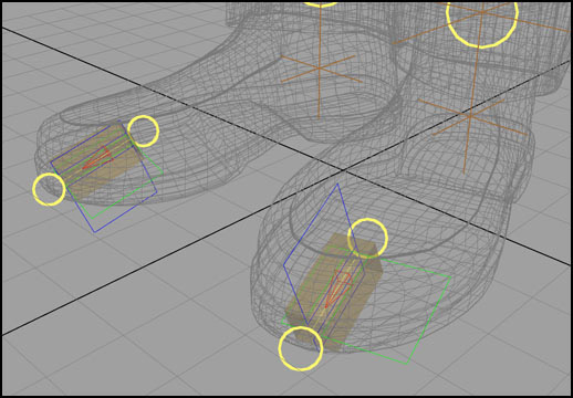
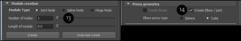
For the both heels, we will create a mirrored joint module as well, but we’ll specify one node per joint module (13) and hence we only need elbow/joint proxy geometry (14).
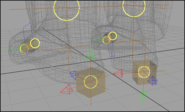
Translating one module in a mirrored module will move the other as well and thus one has to keep in mind that in order for mirrored module to work, the character model has to be symmetrical. Otherwise, you’d have to create the modules separately. We’ll now position the module at the base of the heel.
Spine modules
After building the modules for the legs, we’ll specify the settings to create a spline module. Here, we need five nodes (1) with a start length so they’re spaced appropriately. It will be created on an XY plane (2) with aim axis as X (3) and plane axis as Y (parallel to the XY plane) (4) with Z axis parallel to the world Z orientation. On a side note, you should always keep the aim or twist axis of a spine joint chain as +X if you’re using the advanced twist control with an IK spline solver in your own rigs, since it only works in that condition. Currently, none of the default control rigs for a spine hierarchy in modular rigging tools use spline IK. For my own reasons, I prefer not to use it. Moving on, we’ll also create proxy geometry for the spline module nodes (5) and this won’t be a mirrored version (6) of this module since we’re forming a single spine.
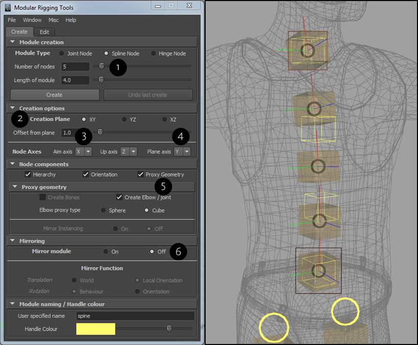
Above -
Left - Settings for creating the spline module for spine as described.
Right - The spline module. Notice the node orientation axes curves are oriented locally.
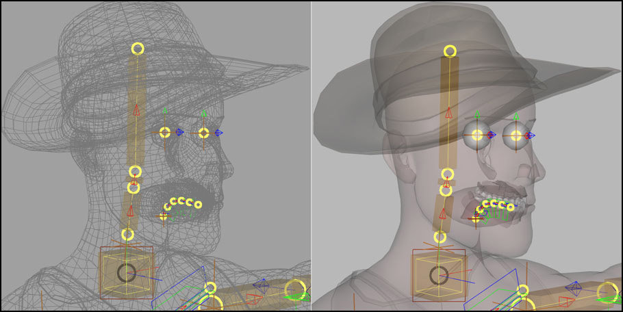
The spline module has some useful attributes that we have to consider. If we select the main module transform for the spline module (the dark brown square control at the bottom, the lighter brown square at the top is the secondary module transform) and take at the channel box, a number of custom attributes are displayed (these are module attributes). From them, you’ll notice an attribute called “Node orientation type” which defines whether each node will have a local or world orientation. For a character spine, it is best to choose world orientation for spine joints since it’ll work better for twisting of the spine along with the character geometry. From the figure above on the right, you can clearly see that each node is oriented locally. We can now change the attribute to apply world orientation to each spline module node.
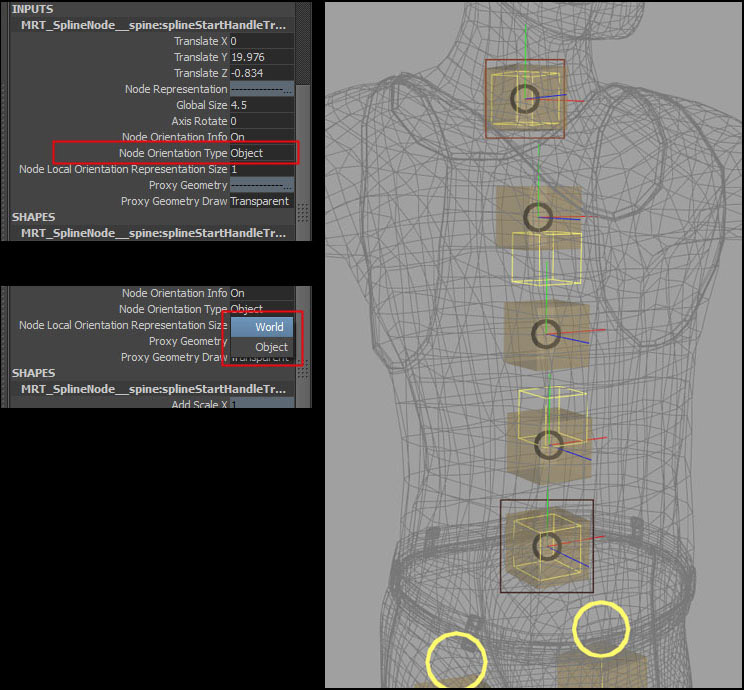
Above -
Left - Modify the spline node orientation type.
Right - Notice the node orientation axes curves are now oriented to world.
When you’re trying to adjust your spline module nodes to fit inside your geometry you might notice that some of the nodes might flip in orientation if they are oriented locally, which is undesirable. You will see it with the three colored axes representation for each node which shows its current orientation. If that happens, you simply have to select the colored axes representation control (you can’t transform it) which are flipped, and change the custom attribute in the channel box name “Tangent Up Vector” from “Original” to “Reversed”. Then its orientation will be correct.
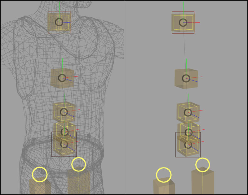
The spline module is now adjusted with correct orientation for its nodes and positioned correctly (see below).
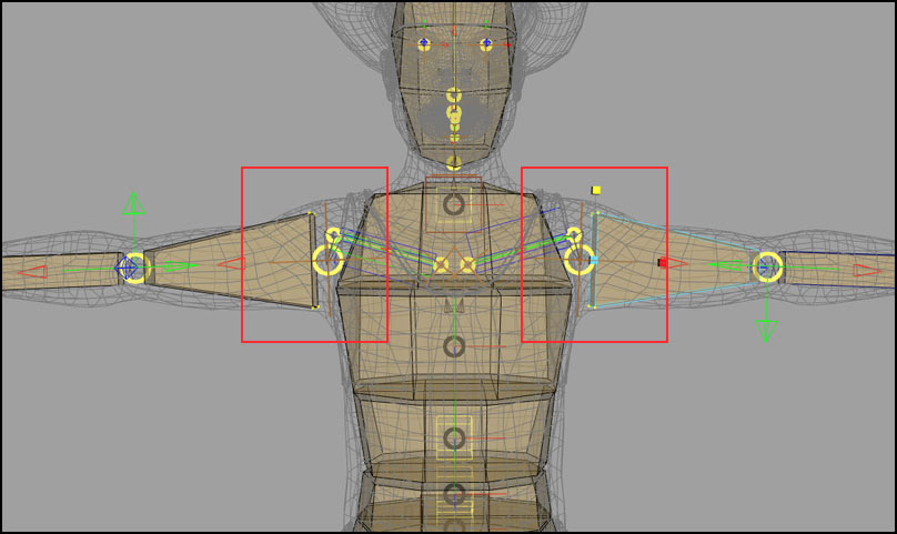
Arm modules
Now, for the both lower and upper arms, we have to create a mirrored hinge module on the YZ plane (7), again with X as the aim axis (8) and Y as the plane axis (9) since we want the final elbow joint to rotate along the Y axis. For your own preference, you could keep Z as the plane axis as well. Also, we’ll specify proxy geometry (10) along the length of the module (bones) (11) and turn on mirror instancing (12). The mirrored module is built with “World” and “Behaviour” (13) for its translation and rotation function settings, which are needed for generating the final joints.
The arm mirrored module is scaled and its nodes are translated with reference to the character geometry.
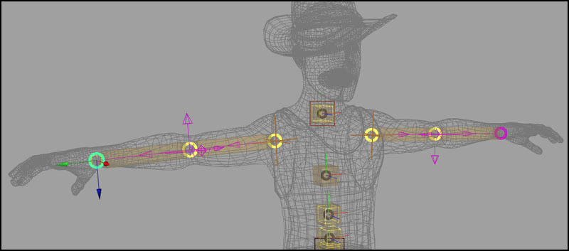
The hinge mirrored module for the arms with reference to the other modules. You can see that the local bending axis for the elbow (the Y axis represented by the green arrows) are opposite to one another. This will give the desired rotation for the final elbow joints on both arms and they will both revolve in a “mirrored” fashion.
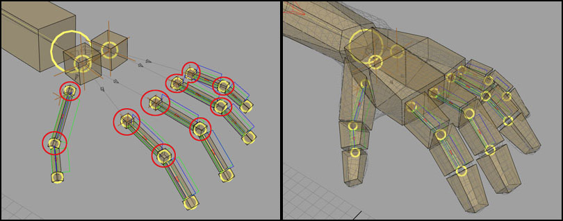
Hand modules
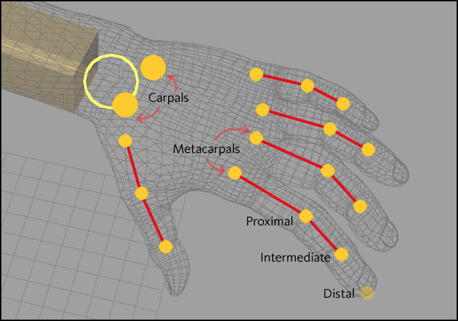
For the hands, we want to build a collection of mirrored joint modules. Here we have to consider which joints will deform the geometry when they are generated. Therefore, five separate mirrored joint modules for the fingers will be created. For a finger, the metacarpal, proximal and intermediate joints will influence the geometry (see below). The distal joint is merely a placeholder and won’t be considered. For the hand the two base carpal joints will allow deformation such as cupping for the palm of the hand.
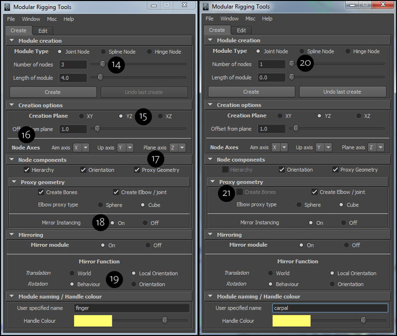
For the module creation options for the fingers with mirrored joint modules, we want three nodes (14) per module with a start length, created on the YZ plane (15) with an offset since our character model is symmetrical along the X axis. For the node axes, we can keep default values with X as aim, Y as up and Z as the plane axis (16). We also want to create proxy geometry (17) along the length of the fingers and on the joints, with mirror instancing enabled (18). We can also keep default values for mirror functions (19). For the two carpals, we will create two mirrored joint modules with a single node (20). All the other options will remain the same, except that there will be no bone option (21) for proxy geometry.
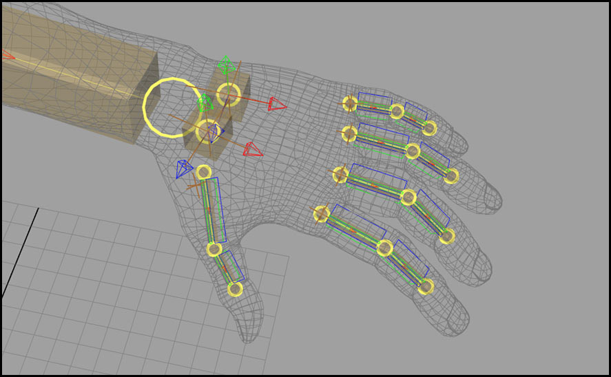
The hand modules for one hand is manipulated and positioned in place. A tip for creating all the finger modules is to create a mirrored joint module and then duplicate it four times with a relative offset (see the documentation for module duplication under the "Edit" tab).
Clavicle modules
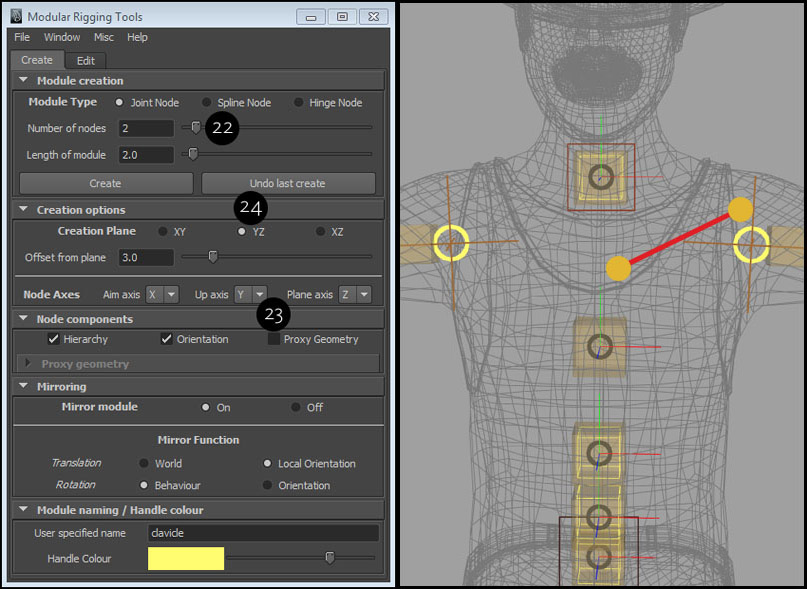
After building the arm modules, we will place the clavicle modules to connect the arm to the spine. It will consist of a two-node (22) joint module, whose one end will rest on the shoulder (acronium process) and the other end will be close to the chest (sternum) (see below right). The module creation options will be default with no proxy geometry (23) , except that it will be mirrored on YZ plane (24) with an offset.
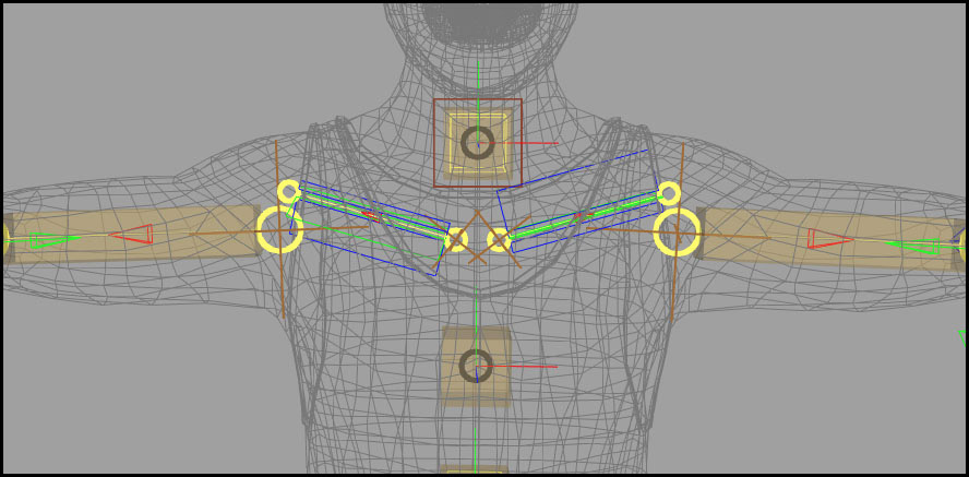
The mirrored module for the clavicles is placed.
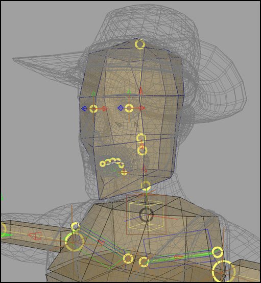
Neck / Head modules
For the neck and head modules, you can now place joint modules using similar technique. For the eyes, one can use a mirrored single node joint module.
Module parenting / relationships
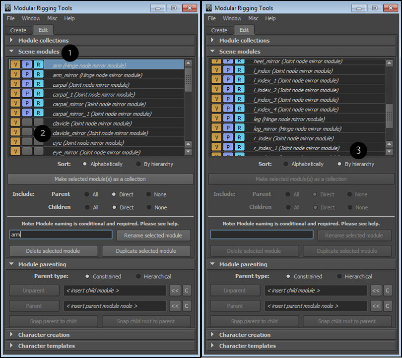
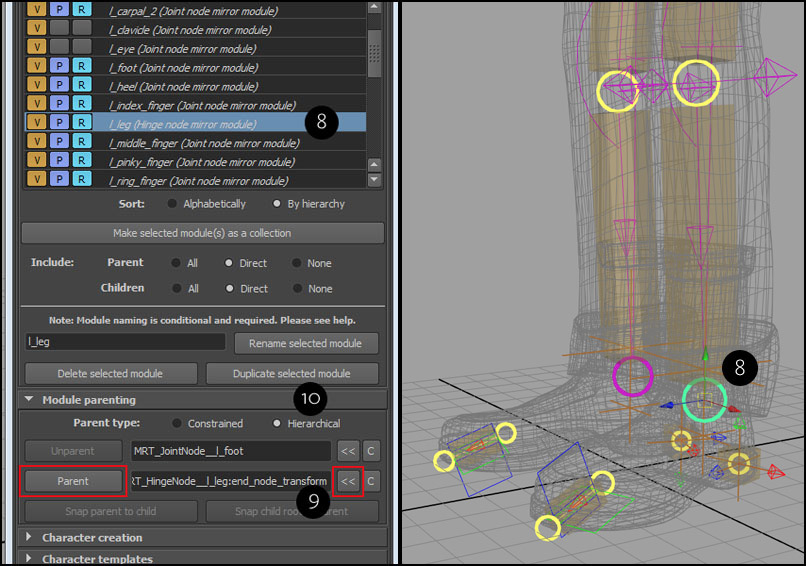
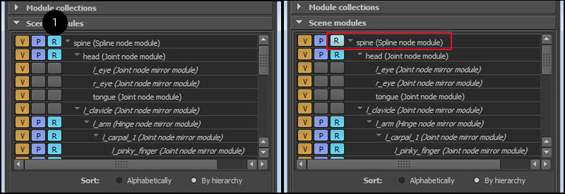
In this part, we will set up all the relationships between the character modules. A relationship or parenting between two modules is a way to define how the final joints generated from the modules will be connected or related. If you have two separate modules, but you want them to be a part of a single hierarchy, you need to set-up a hierarchical relationship. If you want two separate modules to generate joints which won’t have any DAG relationship but you still want to have a parent-child behaviour which can be toggled, you need to set-up a constrained relationship. But before setting up any relationships, you need to make sure that all the modules are named correctly (You can rename after setting up relationships). If you take a look at the scene module list (1) in the modular rigging tools window under the edit tab, you can see that many of the modules have default/appended names (2) and they do not have any order or hierarchy (3).
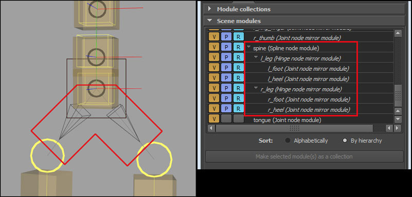
Below - You can now see that the modules have been renamed. The type of the module is indicated within parentheses next to their names.
To set-up a relation or parenting between two modules, you have to insert the child module and a node from the parent module. A parenting relationship will be made from the root joint of the child module to the node of the parent module. A child module can only have a single relationship but a node in a parent module can have any number of relationships. Here’s a list of module relationships/parenting that have to be set up between the character modules.
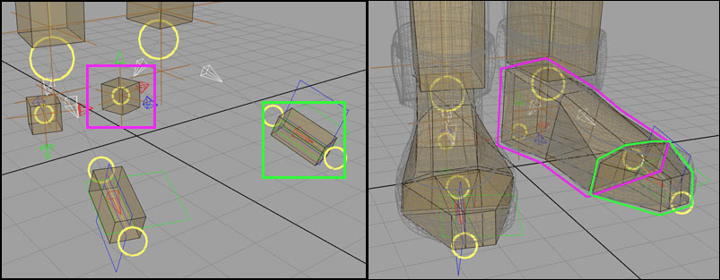
Foot, heel and leg modules
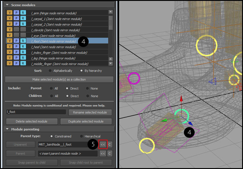
The foot, heel and the leg modules will have hierarchical relationships (and not DG connections) since we want the entire leg hierarchy to work with a reverse IK control rig if needed. First, we select any part of “l_foot” module (4) and insert the selection into the “child module” field under module parenting (5).
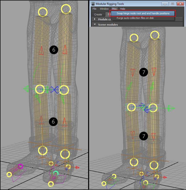
If we look at the “l_leg” module you will notice that its current node hierarchy is reversed, indicated by the red arrows (for X aim axis) (6). To reverse the node hierarchy in a hinge module, select it, open the Modular rigging tools window and then go to Misc -> Swap hinge node start and end handle positions. If you have a mirrored hinge module, reversing the node hierarchy in a module will reverse the hierarchy on its mirror as well (7).
Now, you have to select the end node for the leg hinge module (8) and insert it into the “parent module node” field (9) under module parenting. Then select the “Hierarchical” parent type (10) and press “Parent”.
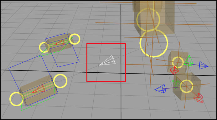
We can now see that a relationship has been set-up between the foot module and the end node of the leg module. A hierarchical relationship is indicated by a “white” arrow (see below).
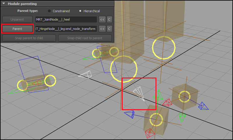
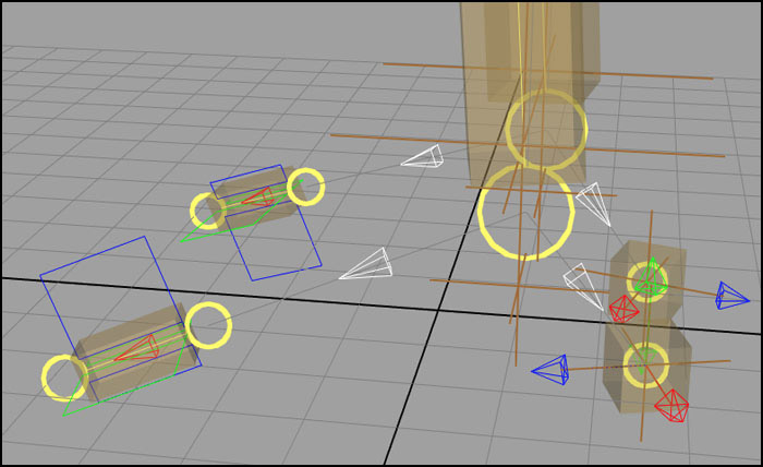
Similarly, set-up a hierarchical relationship between the heel module (which is the child) and the end node for the “l_leg” module (parent module) (see below).
Spine and leg modules
We will follow the same approach with parenting as before. The root node of the spine (spline module) will be the parent, with the leg hinge modules as the children. The parenting relationship will be “constrained” (represented by a black arrow) (below left), since we want the option for toggling the parent connection from the root of the spine. One can detach the leg hierarchy from the movement of spine joints. In the scene module list, you’ll now see that you have parenting relationship between the spine and leg modules (right below).
Arm, clavicle, spine and head/neck modules
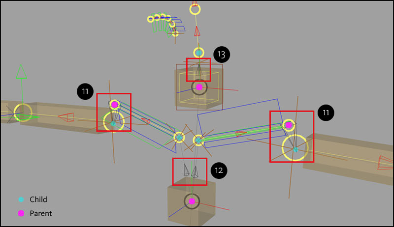
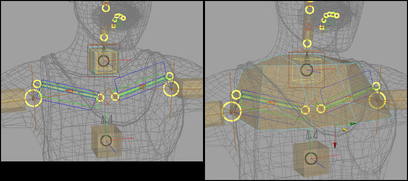
In the figure below, you can see that the root node (representing the shoulder joint) of the arm modules are connected to the end node of their corresponding clavicle modules by a constrained relationship (11). You can also identify the parenting connections among the modules representing by “black arrows”, meaning it’s a constrained relationship. The rule of thumb here is that a hierarchical parenting or a relationship should only be used when needed, if you need two or more modules to be a part of a joint hierarchy. The root nodes of the clavicles in the mirrored joint node is connected to the spine node (second to last) (12), and the neck/head module (joint module) is connected to the end node of the spine (13).
Hand modules
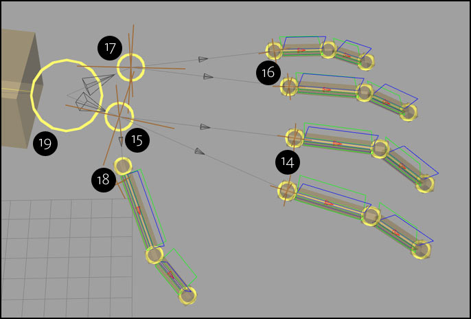
For the hand collectively, the finger modules (children) will be connected to the carpal joints (parent) by constrained relationship. The index and the middle finger modules (14) are connected to the single node of the first carpal module (15). The ring and the pinky finger modules (16) are connected to the single node of the second carpal module (17). The thumb module (18) at last, is connected to the first carpal module. Both the carpal modules are connected to the end node (19) of the arm hinge module, which represents the wrist. This procedure is repeated for the other hand.
Finally, for remaining eye and the tongue modules, they’ll connected to the head joint module nodes. You can consider both the parent head module nodes as the upper and lower jaw joints, so if the upper jaw is rotated, the eye joints will be transformed as well.
All the scene modules are now related by parenting. You can see in the scene module list that the spine module is at the top of the parenting hierarchy.

Modifying module proxy geometry
If created, the default proxy geometry for the scene modules may not be appropriate for the character reference that you may want to build. Therefore, you have to edit the default proxy geometry that gets generated along with the modules. By default, the proxy geometries for the scene modules are in “reference” mode, therefore they can’t be selected and edited. To turn off the “reference” mode for a specific proxy geometry on a module, browse the scene module list and turn off the reference switch (1) (cyan coloured button ‘R’). For an example, you could de-reference the spine proxy geometry and start modifying it. The absence of proxy visibility (P) and reference (R) button in the list shows that a module has no proxy geometry for it.
As you’re modifying a proxy geometry for a module, I’d advise that only apply transformations at the component level on the shape node, and not on the transform. You can also use deformers to modify the proxy geometry and then delete the history on it.
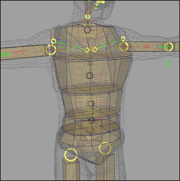
Below - You can see now that the proxy geometry for the end node of the spine module has been modified.
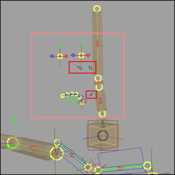
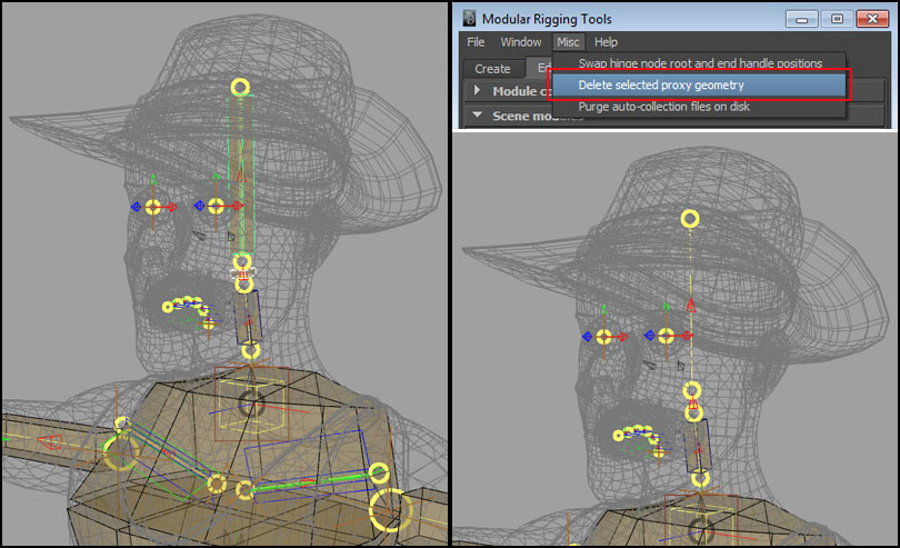
There might a case where you may want to delete a proxy geometry on a module when its not needed. For our current character, we want to build a proxy geometry for a head from a single shape node (polygon mesh). In our head module, we have three proxy geometry shapes on its nodes. If you want to delete a proxy geometry on a module, select the geometry in the viewport, and then go to Modular rigging tools window -> Misc -> Delete selected proxy geometry. Do not directly delete the geometry (see below).
For editing the hand proxy geometry and for my own preference, I deleted some of proxy geometry on the knuckles as indicated (see below left), and modified the rest to match the reference (below right).
For the feet and heel modules, you can modify the existing proxy geometry to fit the shoe reference geometry as shown below.
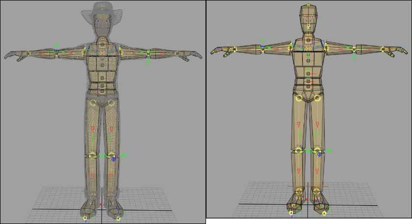
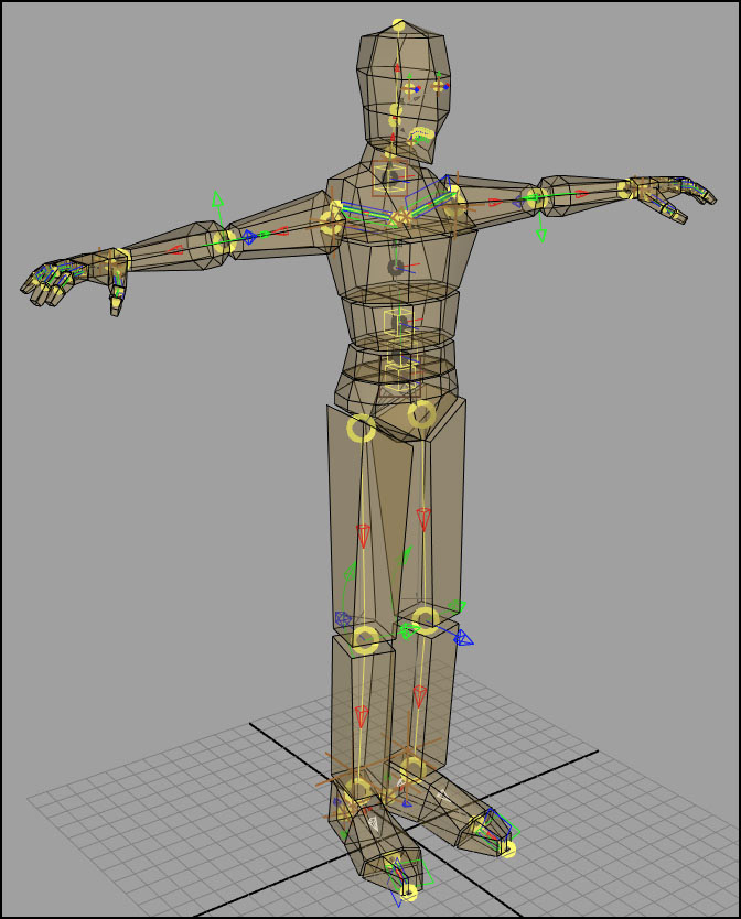
Now, we can work with the other character modules. We finish with modifying all the proxy geometries as shown below.
Save module collection for the entire character
Use the menu option Save all modules as a collection under File in the UI. For more information, see the menu bar options in the documentation.
Create a character from scene modules and save template
Use the button Create character from scene modules under the Rig tab in the UI. For more information, see the character creation in the documentation.
After creating a character, save a template for re-use. See the documentation.
Bind character geometry to skin joints
After creation a character, use the joints under the set MRT_<characterName>_skinJointSet to bind the character geometry. You may wish to use all or limited number number of joints from the set. See the scene hierarchy in the documentation.
Apply control rigs to the character joint hierarchies
To apply control rigging to character joints, see the control rigging for MRT.